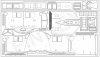
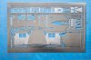
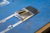
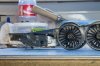
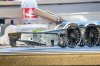
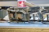
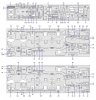
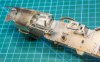
Moving on, just a few small bits to check on the footplate etch and then onto the cab etch.
Sandboxes, hmmmph, the inner ones were junk, the fold up concept didn't work and I got several dimensions wrong, they're in the bin and a revised solution is in progress. The outer ones were much better and fitted perfectly, photos later.
The next big step was the cylinder wrappers and footplate interface, the wrapper has to remain with the chassis, so some sort of hidden joint needs to be employed. Each wrapper has a supporting sub frame to hold it into place.
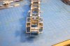
The support frame runs from the motion bracket to the front and supports the cylinder wrapper at these fragile extensions.
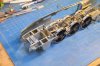
Behind the engine is the footplate with the rest of the valance attached, note square recess to fit over the sand box filler neck and hole in the footplate, the hole is for a retaining screw for the resin body, the screw is hidden inside the sand box filler neck.
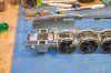
The open holes in the top of the cylinder blocks allow fixing of the castings from inside to give a neat joint outside.
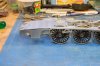
Footplate laid on top of the chassis, the main valance slots in behind the wrapper rear extension at the suitable 1:1 joint, thanks to Sir Nigel for designing this with future thoughts for modelers

The footplate drops behind the rest of the valance and the footplate overlay on top will seal the joint from above, hopefully giving a seamless joint when complete.

The valance covers the reverser bracket, all of this is very tight so care needed when trimming parts and folding up sub assemblies, otherwise nothing fits. Note sand box filler neck covers fixing screw and closes gap to footplate, as per 1:1.
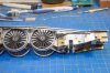
Reverser linkage, the little support bracket is a little mare to fold up, but it does look good and worth the effort, I've set mine for mid gear but by changing the angle of the cab linkage you can set any gear position you wish, the two parts are individual as opposed to being etched as one. Joint strap is a half etch overlay. There's some bolt heads on the valance that need adjusting, the five by the reverser bracket and the two by the reverser arm support bracket. All of these have half etch dimples at the rear which you can punch through to replicate fittings put in backward, I.E nut on the outside as opposed to the correct nut on the inside.

Overall view of the drivers side of the engine.
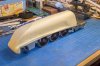
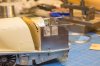
As a quick check I placed the resin body onto the footplate, it lines up pretty well now, there's still a small gap above the cylinder wrapper on this side but that's down to the casting edge and a little trim at the front should close the gap up just fine, I may also just need to drop the very front of the footplate and cylinder wrapper extension by 0.5 mm or so to help it on it's way.
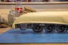
The gap looks bigger than it actually is and nothing is bolted or screwed down but we're getting close to the final shape for everything.

Most importantly the etched cheeks line up perfectly with the resin casting, you can see on the drivers side that the fillet bulges out a little, taking a bit off the bottom to let it sit flat on the footplate will also trim it's width, so I'm not overly concerned at this stage. The small gap between the footplate and cylinder wrappers will be covered by the overlay.
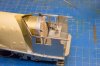
Like thus.
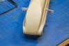
The quick of eye will notice the obvious gap between the overlay and resin shell, Captain cock up and his merry crew were responsible for that, the overlays were not corrected on the artwork for the new correct width Resin shell

Not to worry, the whole sheet has other corrections so it'll just go on with them, that's why we have test builds

MD


 . In addition all the art work (Frames already revised) needed revamping to allow it to fit into a box if required, it's all very well making large A3 sheets which saves on costs but how on earth do you ship them.