Eastsidepilot

Western Thunderer
Ian, Colin,

Fair point and worth considering, however if I was present with a model that require 75% of the chassis to be modified to work in fine scale (which is where the majority of modelers actually lie) I'd be a tad miffed ;)

Your effectively making the majority of modelers suffer for the minority interest group. I think you'd be setting yourself up for some severe criticism by forcing fine scale modelers to have to hack things about to make it work.


Mick D

Then I reckon the Guild o gauge standard for 7mm/ft should be 7mm/ft, (33mm):D:D:D.............but I get your point :(

Col.
 

mickoo

Western Thunderer
Then I reckon the Guild o gauge standard for 7mm/ft should be 7mm/ft, (33mm):D:D:D.............but I get your point :(

Col.
Doesn't sit any easier with me, if I knew of a more elegant solution then I'd use it, right now I can't think of one that's material, time and art work effective.

I suspect in the end the only answer would be two distinct sets of artwork and two photo tools, it's not only the chassis, it's all the cylinders and motion brackets too and if it were a normal un-streamlined engine then smoke box saddle, firebox, footplate, splashers and all that too boot.

Mick D
 

Len Cattley

Western Thunderer
Hi Mick, I like what you are doing for the W1, in regard to S7 and finescale I think you could offer a choice as MOK do. Regarding cylinders and motion brackets you could make them scale to the frames for S7 and make spacers for finescale.
Len
 

mickoo

Western Thunderer
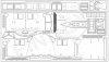
Ok, small update, revised cab etch now finished and off to PPD for printing, hopefully it'll all fit together as there's been a lot of changes and adjustments to suit the new footplate and boiler shell :rolleyes:. In addition all the art work (Frames already revised) needed revamping to allow it to fit into a box if required, it's all very well making large A3 sheets which saves on costs but how on earth do you ship them.

On the plus side, now being part legal owner of Finney rights means I can safely implement some of Martins excellent design principles into the art work. It's sometimes very hard to come up with new solutions to old problems and not copy people who have trod the same path before and run the risk of being accused of plagarism.

Simple changes from the original artwork are fine as you have a base point to work from, but when your adding new parts on top of these revisions then you run the risk of inviting Captain cock up to the party :cool:

Image4.jpg

Hopefully have the footplate art work finished today so that'll be off very shortly too, and then we're back to where we left off a couple of months ago.

I didn't think at the time that simply changing the body shell would illicit so many changes, all for the better of course.

Mick D
 
Last edited:

mickoo

Western Thunderer
A 'windcutter' cab. Was Gresley the only designer in the UK to use these?
Dave, off the top of my head, I think so, the design first appeared on the P2 I think, then perhaps the V2 before the A4.

I think initially it was for streamlining but it was also partly to add larger front spectacle plates, Thompson and Peppercorn applied swept back sheets just in the window area, as did Stanier on the Coronations and Riddles on the Standards.

The angled windows give a larger viewing area and reduce glare, that's the theory anyway.

Mick D
 

mickoo

Western Thunderer
Hi Mick, I like what you are doing for the W1, in regard to S7 and finescale I think you could offer a choice as MOK do. Regarding cylinders and motion brackets you could make them scale to the frames for S7 and make spacers for finescale.
Len
Len, that is one option, but adding spacers only 0.50 mm wide is quite difficult and maintain strength, I purposely moved away from motion brackets and cylinder assemblies that spanned across the whole engine, for one they're not there on the real thing and two, with all the details inside they would just visually and physically impact on all those parts.

Lets be honest here, we're talking about adding 1.00 mm to the whole frame width, that's 0.50 mm per side to bring it out to accepted S7 29.00 mm over frames.

The right thing to do is to make a whole new set of artwork up for S7, I've not fudged or gone halfway house on the O finescale, so I don't think it's fair to offer work arounds for S7 modellers. The original project was never envisaged for S7, just O finescale, with hindsight it could have all been laid out differently, it WILL BE on the next projects ;)

Mick D
 

mickoo

Western Thunderer
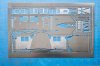
Footplate art work completed.

Image2.jpg

There's quite a lot of reworked parts on this etch as well as a whole lot of new ones like ash pan, new sand boxes, some cab fittings and drain cock levers and linkages.

Now it's simply a case of sitting and waiting for the etches to come back and start test building, usually a couple of weeks. Mean time I need to strip down the previous test build so that I can add these revised parts, notably the front sand boxes and outside cylinder assemblies.

Mick D
 

mickoo

Western Thunderer
Quick update,

Ash pans, I wanted a decent representation of the Gresley wide firebox foundation ring and ash pan, achieving that has been a journey of pain and woe, but the end result seems to fit the bill.

1:-
IMG_6525.jpg

Ok the basic top of the ash pan and firebox foundation ring. Pretty much all perfect, though there are a few errors which will require another photo tool, the errors are quite honestly small, but they're ticking me off and detract from the overall quality of finish.

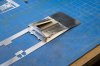
The foundation ring and ash pan are one fold up piece, a small error in the ash pan front face shape leaves a small ledge where it joins the sloped sides, the slots for the rocker arm (I presume that's what it is?) transverse shaft are too long and need reducing by 3mm...to be fair I did think this might happen. At the rear end where the rear firebox sliding support pad is the pan needs cutting, the original idea of bending on two axis didn't work well, it did in 10 thou brass, but 15 thou Nickle Silver is a tad more robust and it didn't sit well on the chassis bearing pads.

The firebox wrapper has a gap at the front where it joins the footplate due to the shape of the top edge as it curves around the corners, just needs extending a little on the art work to make a seamless joint.

On the good side, the rocker arm bearings which are triple folded etch worked very well as did the rocker arm linkage, mind it was bleedin fiddly to make but it does look good. My drain core plugs are a touch too hefty, should really be cut back.

The oval hole is for a mud hole casting, one each side and the small square opening is for a boiler drain tap casting.

2:-
IMG_6529.jpg

Ground level view front quarter, the core plugs clear the valance support bracket and the foundation ring sits just nicely at the front on the support stay, the ash pan sloped base clears the jogged frames over the Cartazzi axle, just...as does the real engine.

3:-
IMG_6531.jpg

Ground level rear view, foundation ring bearing pad sits nicely on the bearing pad attached to the rear frames.

4:-
IMG_6533.jpg

Under frame view, the jogged rocker arm linkage has two dog legs, one at the front to clear the Cartazzi spring safety straps and one at the rear to jog inside the rear footplate support. Inside the rear frame extensions is a pseudo ash pan with front damper flap, which nicely fills up this void, but will make designing the rear pony trucks a bit of a nightmare. I still need to add two small fillets from scrap etch to cover the small gap where the ash pan base cuts across the rear frame extension axle opening, just to close it off and block the light.

5:-
IMG_6536.jpg

Overall rear end view, other than the missing steps and rear pony assemblies this is about it for etch work back here on the chassis.

The new footplate is perfect and matches the Finney A4 body shell at the front end perfectly, more on that in due course.

Sandboxes next, two new inside frame assemblies to test build and then the two revised outer sandboxes.

Mick D
 

mickoo

Western Thunderer
Moving on, just a few small bits to check on the footplate etch and then onto the cab etch.

Sandboxes, hmmmph, the inner ones were junk, the fold up concept didn't work and I got several dimensions wrong, they're in the bin and a revised solution is in progress. The outer ones were much better and fitted perfectly, photos later.

The next big step was the cylinder wrappers and footplate interface, the wrapper has to remain with the chassis, so some sort of hidden joint needs to be employed. Each wrapper has a supporting sub frame to hold it into place.
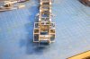
IMG_6550.jpg
The support frame runs from the motion bracket to the front and supports the cylinder wrapper at these fragile extensions.
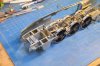

IMG_6548.jpg
Behind the engine is the footplate with the rest of the valance attached, note square recess to fit over the sand box filler neck and hole in the footplate, the hole is for a retaining screw for the resin body, the screw is hidden inside the sand box filler neck.
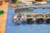

IMG_6547.jpg
The open holes in the top of the cylinder blocks allow fixing of the castings from inside to give a neat joint outside.
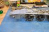
IMG_6546.jpg
Footplate laid on top of the chassis, the main valance slots in behind the wrapper rear extension at the suitable 1:1 joint, thanks to Sir Nigel for designing this with future thoughts for modelers :thumbs:

The footplate drops behind the rest of the valance and the footplate overlay on top will seal the joint from above, hopefully giving a seamless joint when complete.

IMG_6545.jpg
The valance covers the reverser bracket, all of this is very tight so care needed when trimming parts and folding up sub assemblies, otherwise nothing fits. Note sand box filler neck covers fixing screw and closes gap to footplate, as per 1:1.
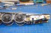
IMG_6544.jpg
Reverser linkage, the little support bracket is a little mare to fold up, but it does look good and worth the effort, I've set mine for mid gear but by changing the angle of the cab linkage you can set any gear position you wish, the two parts are individual as opposed to being etched as one. Joint strap is a half etch overlay. There's some bolt heads on the valance that need adjusting, the five by the reverser bracket and the two by the reverser arm support bracket. All of these have half etch dimples at the rear which you can punch through to replicate fittings put in backward, I.E nut on the outside as opposed to the correct nut on the inside.

IMG_6542.jpg
Overall view of the drivers side of the engine.
IMG_6539.jpg
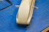
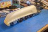
As a quick check I placed the resin body onto the footplate, it lines up pretty well now, there's still a small gap above the cylinder wrapper on this side but that's down to the casting edge and a little trim at the front should close the gap up just fine, I may also just need to drop the very front of the footplate and cylinder wrapper extension by 0.5 mm or so to help it on it's way.
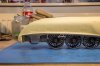
IMG_6540.jpg
The gap looks bigger than it actually is and nothing is bolted or screwed down but we're getting close to the final shape for everything.

IMG_6538.jpg
Most importantly the etched cheeks line up perfectly with the resin casting, you can see on the drivers side that the fillet bulges out a little, taking a bit off the bottom to let it sit flat on the footplate will also trim it's width, so I'm not overly concerned at this stage. The small gap between the footplate and cylinder wrappers will be covered by the overlay.

Like thus.IMG_6551.jpg
The quick of eye will notice the obvious gap between the overlay and resin shell, Captain cock up and his merry crew were responsible for that, the overlays were not corrected on the artwork for the new correct width Resin shell :headbang: Not to worry, the whole sheet has other corrections so it'll just go on with them, that's why we have test builds ;)

MD
 

AJC

Western Thunderer
While this is a prototype in which I have no special interest, beyond idle curiosity, and in a scale I don't actually work in, I nonetheless admire the effort that's going on to produce a first class kit. Quite a lesson - for those that want to see it - in what good design takes.

It also suggests that the Finney 'brand' if you can call it that is in safe hands.

Chapeau

Adam
 

mickoo

Western Thunderer
Adam, thank you, the change from some etches for a couple of commission builds (Nick Dunhill) to a commercial enterprise is quite mind provoking.

Example, the chassis etch was orginally all on one A3 sheet, easy to produce and send, however, you can't get it in a kit box, so the whole chassis needed revamping so that it splits down into a box.

It actually only started out as a set of cab etches to replace the heavy DJH cast monstrosity, but on receipt of the detailed NRM drawings I simply could not resist a new chassis and one thing led to another.

Everyone on the team has a strong view on what makes a good kit, so designing it becomes quite easy, you have an immoveable target to aim for so it's simply a case of fixing all the errors until you consistenly hit the target. To be fair the existing range and build concept is very good and all I'm adding are the extra fiddly bits.

Good design is simply common sense and an orderly build process, coupled with good instructions, something else the team has very strong views on.

So yes, we like to think the range is on good hands, not just the existing items, but new ones too. The next project is in advanced stages of data collecting and the one after that too has been set out in basic requirements, so always something new to look forward too. Both should progress much quicker from lesson learned in the W1 build process.

You could argue that laying things bare to the world is perhaps not the most sensible thing to do, but the thread started as a publicly open venture and it'd be wrong to shut off further updates simply because it's now a commercial venture. Besides, as you note, it gives others a good idea of what goes on behind the scenes, and lets be honest, it's not ICBM's we're designing here ;)

Mick D
 
Last edited:

mickoo

Western Thunderer
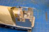
On to the cab, just for a change of scenery.

At the moment most parts are just clipped into place or just loosely positioned so any gaps should go once all soldered into place.

IMG_6579.jpg
Overall view of drivers side, not a bad fit and the footplate gap will close up when it's all soldered into place. The view shows the difference in length between the A4 and W1 firebox sizes.

IMG_6580.jpg
Rear 3/4 drivers side, fall plate fits and the chequered effect has come out well, firemans seat in place and windows with the rear one sliding to suit your whim. There's an additional strip to go along the bottom of the window frame to lock in the sliding frame once it's all been painted and glazed, currently the window slides in a shallow trough, the upper trough being much deeper allows the window to be lifted up and the base flipped out of the groove to allow it to be removed. The window frame is a laminate with a slot in the top to allow glazing to be slid down once its all painted.

IMG_6581.jpg
Slightly elevated view to show cylinder drain cock lever brackets and such like, all very fiddly but looks the part. Note gap between back head and cab front, this will be filled with the correct profile etched part which will shunt the back head toward the rear and it's correct position. I've copied the A4 shape as a test piece and think....not checked the drawings in detail as yet, that this etch may be too small and the A4 back head may also sit too far forward.
At the front top of the window frame is the slot to drop the fixed piece down into the frame once it's all painted. All of the floor surfaces will be covered with a thin wood veneer sheet to give a more realistic effect.

IMG_6582.jpg
Firemans side, cab to resin firebox interface fitting test, the slope and upper arc are pretty well spot on, though the etched flange on the cab front is a touch too thick and needs trimming back about 0.20 mm. The shoulder between the small vertical part of the firebox and sloped section also needs moving up top match the resin firebox shoulder. The gap beneath the resin fire box above the footplate will be closed up once the extension piece is put into place.

IMG_6583.jpg
Driver side, cab to resin firebox interface fit, same notes as previous image, but importantly the roof arc and hump arc all line up with the resin casting.

MD
 

mickoo

Western Thunderer
Ok, it's been over a month since the last update, things are ticking along in the back ground and a new set of cab and footplate etches have arrived, hopefully all present and correct ready for production.

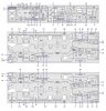
First off however, is a revamping of the instruction sheets, the revised parts have been added to the new sheets, rather than keep redoing the original and very large chassis sheet, this has enabled the original chassis sheet to be re jigged to fit inside a standard kit box for sale.

Thus we now have a new chassis parts sheet
INSTRUCTIONS W1 Chassis.jpg

And new footplate parts sheet.
INSTRUCTIONS W1 Footplate.jpg

The part numbering now allows me to make a start of the footplate instructions as I progress the latest etch build, once built and instructions finished that etch is signed off and ready for reproduction. Following that in very quick succession will be the cab parts sheet and instructions.

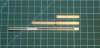
One of the new parts on the footplate etch are slide bar assemblies, traditionally six or seven laminated parts in the vertical plane. The gap between upper and lower slide bars for the cross head is less than 1.0 mm which make filing smooth all those cups rather awkward.

I figured it'd be easier to have the cross head bearing surfaces already flat and smooth by making the lamination's horizontal, thus all the cusps would be on the outside faces and easier to clean up, the two inside faces for the lower T section are easier to clean up as the gap between them is 1.50 mm, but even so, they are not overly critical as bearing surfaces.

The new slide bars are made two pieces, an upper and a lower, the upper has an additional half etch layer to bring it to the required thickness.

IMG_6786a.jpg

All of the bends are on the outside of the parts and are cleaned up once it's all soldered together, except the top bend which forms a lug to slot into the rear cylinder face. The single hole at the front is for a locating spigot from 0.70 mm nickle silver rod to ensure the front end is in alignment when soldering the two parts together, the rear end being aligned by a broach or suitable drill bit through corresponding holes, or more NS rod if you choose, just make sure it doesn't get soldered in there! As you need the rear holes later.

IMG_6789.jpg

Once assembled the front fixing flange is folded up and attached to the front end, the webs are then bent to let the stuffing gland slot in and the whole assembly can then be fitted to the cylinder rear face.
IMG_6794.jpg

Finally, not shown here, a small fillet will be added to the rear end between the upper and lower slide bars to seal in the cross head once it's all cleaned up and made good, small holes in the upper and lower parts (noted above) are there to insert some nickle silver rod to represent the fixings on the real item and fix it all into place.

IMG_6800.jpg

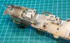
Test fit onto the engine.

Overall the experiment worked well, it was easy to fold up and solder and even easier to clean up the cusps to give nice smooth faces, because there are less parts, there's less cusp and less solder, ergo quicker to clean up. More importantly, the upper surfaces...the ones we view the most in our gods eye view...are perfectly flat and smooth :thumbs:

Mick D
 

Silverystreaks

Western Thunderer
As a long time "Lurker" to this site I was compelled to contribute to this thread with my first post. Having completed a 7mm Finney A4, A3 and V2, I well remember the first set of Finney slide bars I made up for the A4. Subsequently, I was not full of enthusiasm when it came to those for the A3 and even less so for the V2. I therefore have to commend you Mick for coming up with such a fantastic new approach with a result that produces what looks to me like a perfect set of slide bars
Regards
Bob
 
Top