mickoo

Western Thunderer
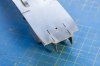
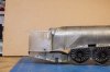
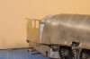
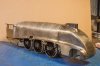
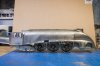
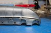
Well that was an interesting exercise :eek: adding the Hachette body to the frames.

Side on the body follows the footplate much better, despite being raised off by the lugs (to be removed) under the body.
IMG_8496.jpg

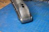
But nose on something is really not right here.
IMG_8497.jpg

The nose is just too thin and doesn't match the footplate at all, curses :rant:

A quick rummage finds the relevant drawing and a quick measure across the footplate at this joint reveals it should be 56.7 mm wide, grabbing the digital measuring stick finds that the Hachette body is 55.3 mm wide which isn't too far out in the grand scheme of things and workable with... a trim of 0.2 on the footplate and an overlay on the side of the buffer casing would solve that. However, the DJH is a whopping double fat burger 59.5 mm wide and of course that's what the etches were measured off.

Basically I need to do two sets of footplate etches, one for the more accurate Hachette and I suspect Finney and retain the remaining ones on this sheet for the DJH shells :headbang:

MD
 

Nick Dunhill

Western Thunderer
Morning Mick
Have a look at some pics of the W1 (and A4s.) The footplate above the cylinder area looks to be a little straighter than you've depicted it in the etchings.
60700%2002-05-58_zpsgi53gxsi.jpg

12088163_162894860721489_439646917233530351_n_zpsqkxhkxtp.jpg

12072664_162894810721494_7486833001656438365_n_zpsmjkcynpo.jpg

60700%201955%20crop%202_zpska9xkmpv.jpg

Also are you sure the footplate is level? does it slope down towards the edge?

Nick
 

mickoo

Western Thunderer
Morning Mick
Have a look at some pics of the W1 (and A4s.) The footplate above the cylinder area looks to be a little straighter than you've depicted it in the etchings.
Nick

Afraid it isn't young man, that's an optical illusion.

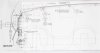
Drawing DN-E-1305 dated 5-5-58 is very detailed in this area.
Image11.jpg

Image12.jpg

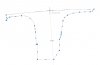
Screen shot from Autocad of cylinder casing etch.
Image22.jpg

I don't know what the radius of the real engine is, it's not marked, so I've transposed it onto drawing DN-E-1305

Image24.jpg

Note at the very front my etch is slightly too high by 0.4 mm, note where it bisects the lifting hole in the frame, mine is through the centre of the hole, the real engine is toward the lower portion, I have raised mine to meet with the DJH body or else even more remedial work will be necessary on the buffer casing.

The plan view clearly shows the taper and how far out the etches are to compensate for the extra width at the front of the DJH casting, not just at the buffer casing but the whole nose is too wide by 3mm, if you taper the buffer casing and the footplate remains a constant width, which it does on the real engine then the nose needs to move in correspondingly.

Image25.jpg

Also are you sure the footplate is level? does it slope down towards the edge?
Nick

Abso - :p - lutely, I've crossed referenced all my photos and drawings with the A4 and give or take an inch (thickness of a line on a GA) or so the front end is 99% copy of the A4 as far as I can tell.
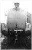
If someone can produce an official drawing that shows the footplate slopes down at the outer edges then I'll amend the etches :thumbs:

Not withstanding the above, then the shot below should be enough proof that the footplate is flat through out it's entire length, in fact exactly like the A4, it is also flat over the top of the buffer casing as well.

Image17.jpg

The source image is in BRILL Vol 11 #11 Aug 2002 page 492, it really is a very good article on the W1 ;):thumbs:

I have one spare footplate etch that fit the DJH shell, the Mk II footplate etch will be modified to fit the more accurate shells on the Hachette A4 and Finney A4.

Addendum,

Just for completeness the A4 cylinder wrapper showing the curved footplate top.

Image18.jpg

Copyright, some geezer on the net :cool:
 
Last edited:

mickoo

Western Thunderer
Yes looks like you're right. My mistake! An optical illusion.:p
Oh ye of little faith ;)

Having said that, I'm not always totally free from 'Captain cock up and his merry band of men' making an appearance :eek:

I was agonising over a few nicks and wrinkles that have appeared on the W1 cylinder wrapper, looking at the A4 above, I needn't have worried at all :cool:
 

mickoo

Western Thunderer
Moving rapidly onward, and after conversations behind the scenes, the front end needs to be revised, so the Mk II footplate is in the process of being worked up, however to speed things along and allow me to get on with the cab at some point this weekend I've simply modified what I have here.

The over-lay won't work as I don't think I'll be able to bend a flat etch to the new curvature, so the rear end under the cab will be cut off to allow me to carry on working at this area. New front end footplate overlays will be squeezed onto a future etch and then butt jointed to the fitted rear to complete these two demo models.

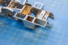
As promised yesterday a photo showing the cylinder wrapper support plate work, this holds the wrapper in the right place and allows the whole cylinder assembly to remain part of the chassis, this avoids ugly joints in the lower wrapper and cylinder faces.

First the ugly side from the top.
IMG_8503.jpg

The support plate is designed to tuck under the slide bar bracket and the wrapper joins to both, the wrapper sits proud of the support plate by 0.5 mm. Once I am happy with the correct angles and such I will dab a bit of solder at the front end where the support plate meets the frames by the lifting hole.

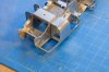
From below and the pretty side.
IMG_8504.jpg

Having trimmed the footplate at the front to the correct width to match Finney and Hachette bodies as well as the official drawing we can see the difference from the original over wide DJH front.
IMG_8505.jpg

I will cut the wrapper support bracket and then bend it in to suit the new width, a small sliver of 0.05 thou on top will strengthen the butt joint. Eventually the footplate overlay will sit on top of this and hide the joint with the cylinder wrapper as well as allow for the very thin lip present here on the 1:1 engine.
 

oldravendale

Western Thunderer
The last few posts are fascinating. Looking at the photos Nick posted I'd have been absolutely certain that the front footplate was flat or nearly so - also that the footplate slopes towards the outer edges.

As you say, Mickoo, not so. Like so many apparently simple and satisfying shapes the actual shape is not simple at all! Still very satisfying nonetheless.

Brian
 

oldravendale

Western Thunderer
In my ignorance..... Is the Hachette loco not provided by DJH as, I understand, was the case with the A3? If so is there any logic to explain why the DJH and Hachette bodies are different?

Brian
 

mickoo

Western Thunderer
Brian,

Yes the Hachette A4 comes from DJH, though that seems to be a common thought, I've never seen anything concrete to prove it.

I think, say think, because I've never seen under the DJH A4, that it's the Piercy A4 shell and that's a whole different model to the normal DJH offerings. Piercy look to be more accurate models and I'm assuming made by someone else and sold by DJH as an outlet.

The DJH shell is one large lump with combined cab, the Hachette is a two part body with etched cab so clearly not from the same molds.

Hopefully over the weekend I'll trim the lugs off the Hachette A4 so that it sits flat on the footplate, it's certainly a much better casting and the sides are nice and straight and the fillet sheetwork much straighter and neater. The problem of taking the lower front lugs off is that they form part of the fixing of the front and rear halves and being mazak or whatever I've yet to find something that'll lastingly fix the two halves together. It's also a complete pig of a material to work with :mad:

I've tried files, slitting discs and cutting discs, within seconds it just binds them all up with waste and due to the lower curve you cannot really get a saw in.

The only down side of the Hachette shell is the WW1 trenches around the front doors and super heater covers which is something I'm still pondering over.

Mick D
 

Richard Spoors

Western Thunderer
Well that was an interesting exercise :eek: adding the Hachette body to the frames.

Side on the body follows the footplate much better, despite being raised off by the lugs (to be removed) under the body.

View attachment 52493

But nose on something is really not right here.

View attachment 52494

The nose is just too thin and doesn't match the footplate at all, curses :rant:

A quick rummage finds the relevant drawing and a quick measure across the footplate at this joint reveals it should be 56.7 mm wide, grabbing the digital measuring stick finds that the Hachette body is 55.3 mm wide which isn't too far out in the grand scheme of things and workable with... a trim of 0.2 on the footplate and an overlay on the side of the buffer casing would solve that. However, the DJH is a whopping double fat burger 59.5 mm wide and of course that's what the etches were measured off.

Basically I need to do two sets of footplate etches, one for the more accurate Hachette and I suspect Finney and retain the remaining ones on this sheet for the DJH shells :headbang:

MD

Just for information, my Piercy A4 is 56.22 mm wide at the same location. My Finney body comes in at 55.48.

Cheers

Richard
 

mickoo

Western Thunderer
Just for information, my Piercy A4 is 56.22 mm wide at the same location. My Finney body comes in at 55.48.

Cheers

Richard
Richard,

Just perfect, the Hachette is 55.2 mm and the real engine is 55.6 mm at this point on drawing DN-N-1305.

On the Mk II etch I've gone with 55.6 plus the 0.2 mm overlay each side giving an overall width of 56.0 mm, modellers can trim off the 0.2 - 0.3 mm each side to fit the Finney shell or 0.4 mm to suit the Hachette shell.

All the best

Mick D
 

delticfan

Western Thunderer
Just come back from working at the nrm today and for what it's worth the dimensions across valances is exactly 8ft on 60007, not sure how that equates to the W1. Thanks to a kind Gresley chap for holding the tape measure, the smoke box and cods mouth were gone so it was quite easy to do. By the way 60103 was next to it freshly painted in Brunswick green and it looked stunning.
 

mickoo

Western Thunderer
Just come back from working at the nrm today and for what it's worth the dimensions across valances is exactly 8ft on 60007, not sure how that equates to the W1. Thanks to a kind Gresley chap for holding the tape measure, the smoke box and cods mouth were gone so it was quite easy to do. By the way 60103 was next to it freshly painted in Brunswick green and it looked stunning.
You did take some pictures didn't you ? how long will the smoke box be off for? I'd like to get up there and get some decent shots of the stays, especially the combination lever stay and the top of the bogie pivot stay.

Your measurement of 8' virtually matches the drawing and scales out at 56 mm across the footplate at this point, exactly what I have set the new etches for. The drawing scales at 8' 1.25", to be honest 1.25" is almost the thickness of the line on the drawing or a nudge of the rule forward by a mm;) I think we're close enough at 56 mm :cool:

All the best

Mick D
 

warren haywood

Western Thunderer
Your not the only one having fun with A4 front ends:confused:
If only that handrail had been left off life would have been so much easier.
I've looked at about 10 different A4's today and no two have the lining the same:headbang:

image.jpeg
 

mickoo

Western Thunderer
Warren, there is a painting drawing for the A4 front ends, but as you've already noted, it was rarely accurately adhered too ;)

I'll make sure the hand rails are removable on my two, one in BR green, the other in LNER blue please :thumbs:

Mick D
 

Overseer

Western Thunderer
Mick,
I have been admiring the amazing job you are doing on the artwork and etches. I have never wanted to build a W1 or an A4 but this does make me think it could be a good idea - but I will resist. Just to add my tuppence worth, I think Nick was right about the straight (flat sloped) sections of the footplate ahead of the cylinders. To me the photos show that the W1 was not built completely to the drawing. It is difficult to be sure with the horizontal curve in the valence/footplate edge but the W1 looks different in this area to the A4.

Also, were the cylinders on the W1 larger diameter than the A4? The bulge in the cylinder cladding seems quite pronounced in the W1 photos but barely there on the A4.

I am looking forward to seeing these complete but think the chassis may be too good for some of the body castings. More refinement of the cladding bands might be needed to make it all fit together visually.
 

mickoo

Western Thunderer
Well on with the etches, having resigned to a Mk II footplate I thought I'd better try the cab, some good, some bad and some WTF were you thinking about designing it like that :eek:

The good, so far, the side overlays work well and the floor pan fits in all the right places, except on one side at the rear I changed the depth by 0.4 mm, sadly to the negative so there's a little gap, then the front didn't quite meet the front faces, not a problem as it's all hidden but the clues were there for when the cab was placed on the footplate, the V front tab and slots don't line up, again not an issue as it's all hidden, but a tad annoying.

The bad, front spectacle surround is too flimsy so that needs beefing up, the RH side sheet for some obscure reason, well not obscure at all, I just drew it wrong! has all the openings for windows, slots and hand rails too far forward by 0.4 mm. The cab seat is wrong, made one up and looked at it and wondered how on earth anyone was ever going to sit in it, it's only 12" wide, a quick check of drawings and most seem to be 15" but Peppercorn seems to have gone wider at 17". At this point a Mk II cab etch was inevitable, which means I can get rid of the WTF's

Side widow surrounds, what an earth possessed me to make a rebate and then an etch to fit in there, especially as you have no control over the etching process, in short PPD need a new egg timer as they clearly left the artwork in the tank too long, even allowing for accepted error it just didn't work, so on Mk II the cab side window surrounds will be relief etched on the overlay. Seat brackets, nice little half etch slots for the brackets, again the brackets over etched and are sloppy in the recess and soldering from the rear through blind holes is difficult, instead I'll just stick them on good old style.

IMG_8531.jpg

Cab side profile, fits well here and the wash out plug lamination's have come out nice, it's all just plonked on so there are some gaps that will go when finally fitted together.

IMG_8532.jpg

Spectacle screen surround too thin but matches the boiler profile better than I expected, this might have to change with the new bodies in mind. The surround does fit in a half etch rebate but only because the front is single thickness and doesn't have a laminate overlay like the sides.

IMG_8533.jpg

Overall 3/4, interesting thing to note here is the cylinder wrapper, from this angle it looks a lot flatter than in full side profile, you can't quite make out the bulge, but it is there and quite obvious from the right viewing angles. The cab front profile matches the boiler shape at the top perfectly, though the rear of the firebox base is wrong I think the top is pretty close on the DJH shell.

IMG_8534.jpg

Side profile, cab looks all ship shape and footplate pretty much follows the correct profile, must get the valances on as that'll pull it all into the final shape to be really accurate.

IMG_8537.jpg

Cab inside, window frames made up nicely and no hidden blunder there, the cab side wall has popped away from the floor, but once it's all soldered up it'll close all the gaps, back head from the Hachette A4, fits the cab V quite well but has slipped over and fallen forward. The reduced height rear of the cab floor can be seen at the back LH corner, despite popping out of the footplate the gap is still there. I'll fabricate some new cab seats from waste etch and make sure the Mk II seats are right.

The footplate rear has two slots to hold the cab floor but they etch really thin on the rear edge, the rear of the cab is virtually flat but does have a little ledge here, not really sure of the best way to deal with that, perhaps just remove the slots and tabs at the rear edge, will sleep on that.

All the best

Mick D
 

mickoo

Western Thunderer
Mick,
I have been admiring the amazing job you are doing on the artwork and etches. I have never wanted to build a W1 or an A4 but this does make me think it could be a good idea - but I will resist. Just to add my tuppence worth, I think Nick was right about the straight (flat sloped) sections of the footplate ahead of the cylinders. To me the photos show that the W1 was not built completely to the drawing. It is difficult to be sure with the horizontal curve in the valence/footplate edge but the W1 looks different in this area to the A4.

Also, were the cylinders on the W1 larger diameter than the A4? The bulge in the cylinder cladding seems quite pronounced in the W1 photos but barely there on the A4.

I am looking forward to seeing these complete but think the chassis may be too good for some of the body castings. More refinement of the cladding bands might be needed to make it all fit together visually.
I agree it looks flat and I agree the drawings show it curved, I also agree that it probably wasn't built to the drawings, it's not a tolerance fit part so near enough would do in the factory.

However when you view the model from the same angles as most photos it looks pretty flat, even viewed side on it doesn't look as bad in the flesh. At the moment the curve is one arc at 95' radius so I might break that into two and do the part ahead of the cylinder and flatten that bit off, but then were only talking fractions of a mm.

If I make the front portion perfectly flat between the front point and front of the cylinder block then it will only be lower than the arc at it's greatest point by 0.2 mm, it may be easier to leave it as it is and let others file that arc to suit their desire, Six on one and half a dozen of another. The RCTS book has some nice but small photos that show it with out doubt curved, but interestingly they look flat'er' once the skirts were cut away, I'll see if I can scan them with out breaking the back of the book. I've also been scouring all my A4 photos and from some angles they look flat as well.

Here's one off the web
10000.JPG

Looks curved....a bit?

Here's a crop from a purchased copyright image.
Image1.jpg

Certainly looks curved, interestingly it also looks like there's a kink or change of radius to the rear section over the cross head area, yet in the image above it looks like one constant radius, I think the acute angle forces the radius, the cylinder bulge is also well illustrated as well as some nice bogie front details which I need to lighten up to bring out.

Cylinders, as built they were 20" but from Dec 56 they were sleeved down to 19" to match the A4's but the block casting remained the original size with bulges.

All the best

Mick D
 

oldravendale

Western Thunderer
Hi Mick.

I have 170 photos of A4s, not including my own. The shape of that casing is indeed complex and it appears to alter depending on the viewing angle. In all the shots of the locos viewed in profile there is no doubt that there is a continuous curve. However, from certain angles it appears that the footplate flattens off in the region of the cylinders and in one or two shots the footplate actually appears to go in to a negative curve. Based on the profile photos - all of A4s I must add - I'm pretty confident that the footplate does not flatten off. Equally, and from other viewpoints, it can be seen that the surface of the footplate is flat and not on a curve once it has left the boiler casing profile. Again this profile can look misleading depending on the viewpoint.

The clincher for me is that photos of the same loco but from different viewpoints can give the appearance of different profiles. I accept that the dates of the shots may be different and that the locos may have been through works more than once between shots but the fact remains that 100% of the profile shots confirm the footplate shape.

Having said this it is interesting and somewhat surprising that out of my collection I only have one of 60700 and the angle doesn't help confirm or deny the absolute footplate shape.

I'd be happy to show some examples but all of the shots I refer to above are copyright of others. However, there are two of mine below, taken of the same loco at the same time which may help to demonstrate the situation, having said which that pipe running along the footplate doesn't help in deciding the profile. The viewpoint here is the same, but one is a close up portrait while the other is from a distance.

60024.  First Shot.  Location & Date Unknown.  FINAL - 1000 dpi.jpg

However, the first is one of my shots of 60024 when in Scottish service, probably on the Perth trains but date is unknown. To my eye that footplate looks flat from above the front of the cylinders to the point where the curve sharpens over the buffers.

60024.  Fourth Shot.  Waterloo.  26 March 1966  FINAL.jpg

This shot, of the same loco at Waterloo on 26th March 1966 seems to confirm it.

60024.  First Shot.  Waterloo.  26 March 1966.  FINAL.jpg

But this one indicates a continuous curve.

60011 remains at Darlington Works.  3 October 1964.  Photo Brian Dale - Copy.jpg

The clincher for me is this one, though. The sad remains of 60011 at Darlington Works Yard on 3rd October 1964.

All my copyright except 60024 in Scotland which is in my collection but not by me.

Brian
 
Top