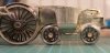
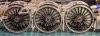
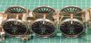
mickoo

Western Thunderer
Nearly there, valve gear all laid out, just needs tabbing up in an etch and sending off :thumbs:

Image2.png
Schematic view for the instructions, I think I might flip this as the lubricator linkage is on the other side and we're viewing it from the front in the drawing and not behind, flipping this would bring parity to the image.

How this came about is all a bit odd, all my work on the W1 is laid out with the front of the engine to the left, because that's how the works drawings are laid out, however, I've just noticed that the A4, A3, V2 etc are laid out the other way with the front of the engine to the right. I just idly mused why some drawings were the other way around, all drawn in the same era by the same office and over seen by Gresley. The Thompson A2 class and Peppercorn A1/A2 revert back to the W1 format with front to the left?
Image1.png
Parts laid out ready for tabbing up, they'll get shuffled around to minimize real estate and tighten things up and group things a little better, I.E. lubricator linkages, 2:1 linkages etc.

Enjoy.

MD
 

mickoo

Western Thunderer
words do not do this justice WOW
Thank you,

I'll find out in an hour or two if the metal work looks as good as the art work :cool:

The plan is to build the bogie and trailing trucks this weekend, then brakes and valve gear next during week. Hopefully the demo model should look much more advanced at the Bristol show next weekend. Photos here first of course;)

The Finney7 40:1 motor and gearbox arrived this week as well for trial fitting and clearance testing, so it's all coming together rather rapidly.

There's still a few castings to work up and get a test run as well as the casing to finalise.

MD
 

S-Club-7

Western Thunderer
Have you run a set off yet to see if they form correctly, mind seeing some of your other work I see no reason why these basic shapes won't form correctly at all.
Although drawn several months ago I keep forgetting to add them to my Shapeways orders! Will have a set or two available at the S7 meeting at the end of the month.
 

mickoo

Western Thunderer
Hi Mick, will you be able to make the coupling-rods jointed like the real thing?

Len
Stupid boy Pike, go to the back of the class :cool:

In all seriousness, it wouldn't look good if Finney7 produced rigid coupling rods now would it ;)

But to answer your question, of course you can, if you choose to :thumbs:

MD
 

mickoo

Western Thunderer
Ok, etches arrived today and on quick inspection seem to be all tickety boo, so time to crack on with some building....only to find my lit magnifier has just died....perfect timing!

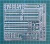
Anyway, as it's daylight, couple of photos of the first test etch, theres two lots of brake gear on the bogie one, one set is all individual parts for people to pin and make up, the other has some short cuts with layered etches, we'll see which looks best/viz ease to build before deciding on which way to go.

IMG_9373.jpg

IMG_9374.jpg

MD
 

mickoo

Western Thunderer
Would any of these etches be available as separate items Mick ? as apposed to being in the main kit.

Col.
Which items were you thinking of?

The valve gear is a different material thickness to the rest of the kit so has been designed as a stand alone etch. It should also be suitable for the A4 on which the W1 was based (certainly motion and wheels etc) and the A3 but I'd need to check things like lubricator linkages as I know they are different on the A3. It may be possible to squeeze the extras in onto one generic A3, A4, W1 sheet sort of thing.

Other than that then all the other items can easily be lifted onto a bespoke sheet, I often have test sheets going off, so if there were some bits you specifically needed then we could come to an arrangement regarding the costs.

MD
 

mickoo

Western Thunderer
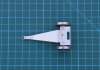
Small update, the trailing end, it was always going to be a mare back here, and so it was to be. The problem is trying to keep things as close to 1:1 and make it manageable in 1:43 and the Cartazzi axle vexed ze little grey cells the most. An arched (still a possibility) axle box carrier is one option but allowing it to slide and be sprung present one too many factors to accomodate....for the time being. I've found that making something one way and seeing it in 3D often unlocks another solution.

So the current solution is a fixed lateral axle box assembly where side play is controlled by washers, in all fairness, the W1 Cartazzi is very close to the rear drivers so the angled slide would be very shallow and normal side play is probably more than satisfactory in 1:43 scale.

IMG_9386.jpg

So this little unit slides in the frame guides up and down, the two wire spigots entrap the springs (odd ones kicking around in the spares box) and the axle box assembly has no side play as defined by the trapezoid shaped plate on top, tapered to fit the tapering frames in this area. The tapered frames ruled out standard axle boxes as they would not be parallel to the axle.

Confession time, the artwork is perfect, it all fits where it was designed to, even down to being nearly 3mm too narrow, as per the design. Some one, some where must have done a really smart thing to counter this dumb mistake :rolleyes:. Anyway, the new slide will be the correct width and allow a maximum of 2mm sideplay which can be reduced with washers and not cut bits of tube like me :cool:.

From above the two spigots pass through the ash pan assembly.
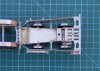
IMG_9377.jpg

This is one of those shots modelers try to hide, there's always a part on the model where the solder tends to migrate and make the model look ugly and messy, to be fair a lot of this was built a year ago and techniques evolve.

The holes in the ash pan are roughly in place, until the axle box went in their exact location on the sloped surface wasn't exactly known, yes yes, those clever at trig could of probably worked it out, I just prefer to poke it and see where the marks are and then drill but the art work will now amended to have these holes in. The sloped ash pan floor does not have any effect on the springs or their ability to work, it all actually works very nicely....amazingly :confused:

The photo also shows clearly the tapered inner frames which negate standard axle boxes or slides, to the rear is the drag box assembly and due to complexity difficult to get into once built up....boxed myself into a corner here...but some kniving and scheming should see a way out later.

Maximum curvature, no idea what it is but it's all y'all get ;)

IMG_9380.jpg

From below the trailing truck is readily visible
IMG_9381.jpg

IMG_9382.jpg

It passes over the Cartazzi assembly and clearances are tight but it does all clear...just :thumbs:

The trailing truck is the correct width and shows up how narrow I incorrectly designed the Cartazzi axle box assembly.

Confession #2, those sharp of eye will not that there's a blanked off arched slot inside the trailing truck under the axle, the plan was to have the screw under there and hidden away :thumbs: But then I forgot that the 3/32" axles need the wheels pushed on and you can't do that once the truck is inside the frames and secured, nor can you secure it with the wheels fitted, bahh!

The solution (current) is a compromise and brings the arch slot outside to the rear of the truck, beneath this is a spring which adds load to the tail end, the screw being fixed to the chassis, which present the real issue for not putting the screw under the axle, being fixed it will impact the screw as it lifts.

Not overly comfortable with this at the moment, it works, works very well actually, but is an empennage on the rear not present on the 1:1 engine, the final design is still under review.

From the rear.
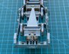
IMG_9384.jpg

The spring and screw which makes the rear end float, slide and tilt, the nut is tacked on the outside as I can't get inside (boxed in noted earlier) to hide it. A single point CSB here would of been ideal, discreet and functional but fixing at the front end would require a re design of the stays to non prototypical shape and the limited clearance between truck and Cartazzi assembly means it'd never work. If I keep the extension plate it'll be rounded off to make it a little easier on the eye and be part of the etch and not tacked on.

Couple of shots of the trailing truck, other than the own goal on the slot it all went together pleasingly well.
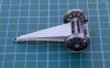
IMG_9389.jpg

IMG_9394.jpg

Right, front bogie next, which compared with the recent trials should be a walk in the park....say's he :cool:

MD
 
Last edited:

Yorkshire Dave

Western Thunderer
The spring and screw which makes the rear end float, slide and tilt, the nut is tacked on the outside as I can't get inside (boxed in noted earlier) to hide it. A single point CSB here would of been ideal, discreet and functional but fixing at the front end would require a re design of the stays to non prototypical shape and the limited clearance between truck and Cartazzi assembly means it'd never work. If I keep the extension plate it'll be rounded off to make it a little easier on the eye and be part of the etch and not tacked on.

If you want to make this fixing discrete why not work from the top down rather from bottom up. I'll try and describe my thoughts using two of your photos above. Whether it'll work or not is another matter.

From the top extend the plate as I've drawn in red (may not be prototypical but it remains hidden) and place the arch slot in this. A threaded tube can be mounted on top of the truck and secured with a countersunk screw (next photo) over the axle around which the spring and washer can be placed. This can then be threaded through the arch slot in the top and a screw into the tube will hold it in place.
Mod 1.jpg

Mod 2.jpg
 

mickoo

Western Thunderer
Dave, yes that is one option and I do follow your logic, the screw is fixed to the truck and a nut added on top to secure, and the drag box assembly modified to have an extension on the top plate with an arched slot.

Couple of problems, the footplate sits flat on top of the drag box so you'd need to add a slot or hole in that to clear the nut as it swings. Worse yet on the underside not seen in the above photos is the dropped section of the drag box, circled red.

IMG_5426.jpg

You'd have to cut that out or make a slot in it, sadly it's not a simple sheet, it's part of the complex folded up drag box, cutting here is pain and with no clearance above, there being several other layers of the drag box above.

However the biggest problem is final assembly, hidden beneath the trailing truck is the main rear end footplate / cab securing screw.

IMG_7888.jpg

If we opt for the fixing from above then we can't access this screw for final assembly, which ever method I choose, it has to go from below and the truck has to be fitted after the body is fitted.

Another option is so simply cut the arched slot in the depressed section of the drag box and not fix from above, but rely on the nut at the front bearing to stop the truck hanging down to far when the model is picked up, however, that's a fair amount of kit hanging off the back on one nut and it won't take too much to stress that fixing or damage something.

Actually whilst writing the above an idea has germinated, details on the rear truck are scant at best so the actual shape is best guess and a bit of logical license so a better option might be to extend the rear wall. The current slot is just aft of the axle by a fraction and the temporary extension piece has to be so far outside to clear the rear wall, if the rear wall wasn't where it currently is then the slot could be placed about half way between the two. a new rear wall would then hide it all.

IMG_9381a.jpg

I'd have to make a bolt on plate for the nut as it will fall directly onto the rear wall of the depressed section, circled yellow in the first image, the green being original and extended nut locations.

That'd actually work quite well and limit major works to etches already signed off.

MD
 

Yorkshire Dave

Western Thunderer
The bits you circled above are what I couldn't see. At least I hope it gave food for thought.

Your last solution is the most desirable option given the circumstances as it places the bolt closer to the centre of the axle for the minimum of effort.
 

mickoo

Western Thunderer
The bits you circled above are what I couldn't see. At least I hope it gave food for thought.
Absolutely, I can see away out of the box now :thumbs: With hind sight and looking at the V2 GA in the mean time (other projects) I suspect the rear truck must have some sort of linkage for side control and weight carrying, thus the extra plate work around the depressed section on the drag beam would probably prototypical, I suspect the truck used swing links or even tapered slides of some sort....it'll be in a book somewhere...which I'll browse post Bristol...to get a better idea of the mechanics in that area and thus a best guess on the surrounding plate work.

As noted above, sometimes you just have to do and see what happens and if it's not quite right it'll often illicit a different idea or thought process, either privately or publicly.

Anyway, onward, the front bogie, as expected, noted, planned, designed no hidden visits from the infamous Captain or general fubars. Six hours later, four of which are probably cusp removal :eek: et viola, one bogie.

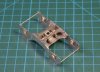
Dead beetle view.
IMG_9396.jpg

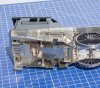
Side control is provided and is frankly very tight, I wanted to preserve the openings in the top free from 1:43 obstructions so the spring length is a bit shorter than desirable, the advantage is that it's quite stiff which is perfect as there is limited clearance on the rear wheel and cylinder casing, hence the V cut at the rear of the outside cylinder blocks (photos tomorrow once it's all fitted).

The webs with holes in the middle support the real side control springs and associated assembly which passes through the oval holes in the transverse stretchers to the pivot pin on the 1:1 engine. The spring casting is as yet to be resolved, as are the dummy axle boxes / hornguide assemblies.

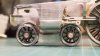
Wheels fitted...loosely, being taper fit they'll get pushed home once it's all fully finished and I need to add the dimple in the end of the axle to centre when wheel turning.
IMG_9397.jpg

Small recesses at the front are waiting for the guard irons to be fitted tomorrow and this is the early style bogie with rods for stretchers, certainly at the front. In later BR life the rod was replaced with an angled beam assembly....which like a muppet I totally forgot, so will add that on the production etch.

Posed under the engine.
IMG_9399.jpg

Pretty much perfect alignment and height for 1:43 clearances and model railway use, just noticed I need to add the axle box retention straps onto the MkII etc.

And other side with out the distraction of crosshead.

IMG_9401.jpg

Yeah, that'll do :thumbs:

Right, kick back mode, beer, food, movie time, more tomorrow hopefully :cool:

MD
 

Big Train James

Western Thunderer
Thanks, but nah, it's all just 2d stuff stretched, sliced, and diced :rolleyes:.

Cut metal, heat with big hot stick, drop from burnt fingers, curse, start again :p

MD
You forgot the dripping of solder on your bare leg.....:eek::eek::eek:...:mad::mad::mad:...:confused::confused::confused:...:(:(:(. Spot on with the rest. Especially the cursing :D.
 

mickoo

Western Thunderer
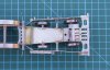
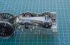
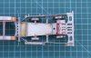
Slow progress today, next up the brake gear, I'd opted for two versions, the full blown monty with each individual linkage all pinned together, and a light weight laminated affair, primarily to make life easier and simpler to construct, didn't turn out like that simpler - yes, easier - doubtful as you end up filing cusps of some awkward shapes. I only made one transverse plank and it looked, well like a laminated set of etches so it went in the bin.

The idea isn't dead, I will think about it and work up a more robust set up.

So it was back to the full monty....only applies to the bits underneath, the hangers and brackets are standard.

So, a lot of work and very little to show really.

IMG_9405.jpg

The hanger brackets are fold up etch to represent the real thing and soldered to the frames, I've opted to tap 14BA for the moment to hold the hangers in place, but may replace with more authentic pins once it's all built up and finally fitted.

The over size rim on the standard wheel makes the gap impressively tight, etched at 2mm wide I had to thin to 1.7 to fit and even then one of the rims just hisses past the bracket at one point, indicating the rim isn't quite true, I'll run it up in the lathe and skim a fraction off so that it clears. If you don't have a lathe then stick it in a drill and just skim with a file; alternatively one could thin the brake hanger bracket.

IMG_9407.jpg

Looking nice and cluttered already so it has promise.

From below
IMG_9409.jpg

It's all pinned and moves like the real thing, you don't have to do that of course but I wanted to see if it was possible.

There are a lot of parts and it isn't the work of a day or two but i just gave the boss the Credit Card and sent her shopping, stuck some tunes on the head phones and zoned out, it's surprisingly therapeutic and not at all hard once you get to grips with it.

The main planks are double lamination as are the two small equalizing beams, the rest is single lamination, pins are 1.0 mm and the pull rods 0.8mm, the hardest part is forming the yokes at each end of the pull rods, the etch does have a small hole in the end to aid drilling out once folded for the 0.8mm rod to fit in.

None of the pins are soldered yet and I may just dab a bit of glue under a few key points to lock it into place once it's all finished and in the right place.

The trick is to make the holes in the etch work a tight fit on the the pin, I drilled to 0.9mm and then gently opened with a broach until the 1.0mm rod was a tight fit in the hole, assemble the bit your working on, yoke or equalizing beams and then cut the pin to near the right size but slightly over. Then I put the pin in the vice between the jaws and gave it a good tighten, being brass the pin swells and grips the etch work even tighter but importantly on either side outside of the etch work it swells more; it's a sort of mild riveting process and the pin will not come out easily.

Simple technique and avoids the use of solder and endlessly cleaning up afterward :thumbs:

I'll not get all of the brake gear done by Bristol so will just do the next section to the leading driver and perhaps the next bit to the front brake shaft, then switch to the valve gear.

Is it all worth it? I think so, it's not any more fiddly than valve gear, just repetitive and being easy shapes very quick to clean up the cusp. I will confess I wasn't looking forward to it, but once you break it down to it's component parts it's actually quite easy.

MD
 
Top