FSIJ - 16mm narrow gauge

Greengiant

Western Thunderer
Baseboard construction continues and ground form starts to make an appearance.

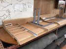
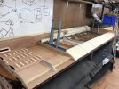
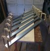
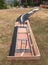
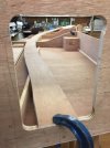
Final piece of scenic section trackbed now installed, four of the six scenic boards are in this photograph. This view is from the RotaYard boards.
IMG_0378_zpsku0ldtv0.jpg

Using a lot of this stuff to stick down the foam.

IMG_0379_zpsbn09xh4x.jpg

Gorilla glue expands to three to four times its volume and also acts as a filler that can be carved, sanded and painted. Sticks like the proverbial to a blanket!

IMG_0372_zpsifncglx5.jpg

What you must remember to do is make sure location dowel holes are covered at the rear!
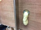
IMG_0419_zpswfp7gain.jpg

Some of the boards with foam waiting to be stuck down.
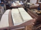
IMG_0417_zpsnmfzrglo.jpg

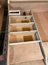
Trunking for the wiring is also installed along with aluminium tube to hold the point rodding.

IMG_0416_zpsk5gjoilc.jpg

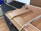
Very therapeutic shaping this with a Surform, makes it very easy, sometimes too easy.

IMG_0374_zpsiveihnr2.jpg

The final scenic board now has the foam cut ready to be glued in place.
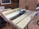
IMG_0484_zps9h2e2acs.jpg

Martin
 

Greengiant

Western Thunderer
We did not go with our original design of metal gondola support brackets, instead we went for CNC'd Birch ply.

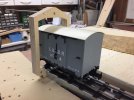
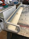
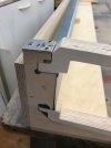
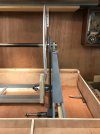
The prototype gondola support bracket has been CNC milled from plywood and has passed all weight and stress tests. The track base on the gondola is trunking bought from Screwfix.

IMG_0476_zpsqgtxmhi8.jpg

Here shown with some stock in place to show clearances. You can also see the sides of the trunking are not at 90 degrees to the base, this we had to allow for in our design.

IMG_0482_zpszvfn6zud.jpg

IMG_0483_zpscazx4wyn.jpg

Now we can go ahead with production of the twelve supports and construct the RotaYard.

Martin
 

Greengiant

Western Thunderer
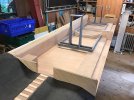
Construction has at last started on the final two boards of the layout, these are the ones that will be supporting the RotaYard.

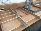
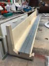
The mid-joint cross pieces gets quite thin at one point, this has been compensated for by beefing up some of the other surrounding structure materials.

This is a mid-joint cross member with all the machining done.

IMG_0509_zpsghbpdmi5.jpg

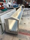
One element beefed up is the 3mm ply sides for the front channel, these have been upgraded to 12mm square softwood.

IMG_0510_zpsjcbqsx8u.jpg

Then topped off with 12mm ply rather than 3mm ply.

IMG_0511_zpsvc3ed10q.jpg

This did involve some thinking on how to get it all clamped while the glue dried!

IMG_0513_zpsikknibcj.jpg

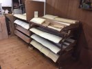
Now the scenic boards have the foam in place and carved to shape, some form of safer storage was needed, so to this end some old bits of Dexion came in handy to make a supporting frame for the boards.

IMG_0515_zps5ybfwg6q.jpg

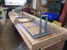
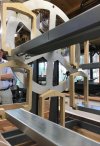
Now the basic structure has been made for the RotaYard support boards, more detailed construction can take place using the main metal frame as a guide to where all the elements should go.

IMG_0516_zpssocgknfk.jpg

We will be welding on some adapted Spur shelving brackets for the main uprights.

IMG_0517_zpsnu98ka61.jpg

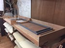
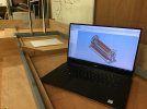
Here you can see the beefed up front beam of the baseboard supports the frame full length, some softwood timber will be machined to support the full length of the rear frame. Also the CAD of the RotaYard can be seen on the laptop, which we use not only to create working drawings for the construction but also to check it will work and all clearances are sufficient.

IMG_0519_zpslytxjrng.jpg

Martin
 

Greengiant

Western Thunderer
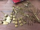
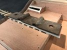
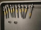
Meanwhile as the baseboards and RotaYard were progressing, we received a lot of packages containing cast chair baseplates, slide chairs, pandrol clips and baseplate bolts, all made from our own patterns.

IMG_1011_zpsud3yfduw.jpg

A close up of some the castings. We have a good few evenings work cutting these from the sprues and cleaning up.

IMG_1012_zpsscd3sl61.jpg

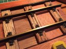
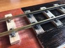
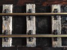
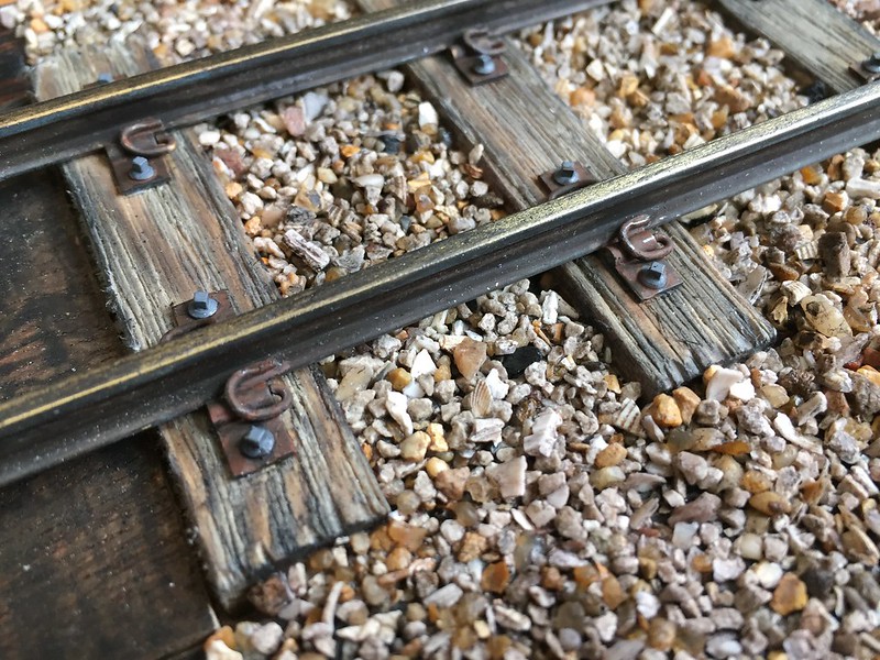
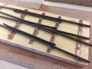
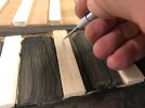
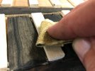
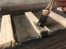
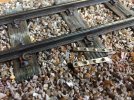
Development work has been going on with the sample track section, on this we are working out techniques for painting and ballasting the track. Initial sleeper distressing and blackening of track and fittings. this test piece is using some brass rail we had, the layout rail will be nickle silver.

27385866958_596ecace45_c.jpg

A smaller section I was working on a few posts back, has had some more colouring and ballast added.

40363275785_46dca8d08b_c.jpg

This set the method for the main test piece, here shows it 'as built' and 'coloured up' side by side with a black undercoat where the ballast will eventually go.

27385870108_ed59b7fbb3_c.jpg

A few more sleepers as they are developed.

27385872288_efdaf8a7c0_c.jpg

27385871338_90b6177ec9_c.jpg

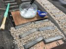
Some ballast has gone down, for this we used chicken grit, only a couple of pounds for a big bag, enough to do the layout. It sizes up a bout right, has enough tonal variations which will then carry through with various washes and filters to bet it near the Bredgar ballast.

40363279265_9649fc3606_c.jpg

Here I have started to work on some more sleeper colouring and the rail fixing plates and clamps. Studying the real thing and blowing up reference photos, I had not noticed before, but the cast fixing bolts hold a distinct grey hue when dry, so this had to be replicated.

41215490992_c1718342f6_c.jpg

Because of the dappled shade that Stony Shaw Station resides in, much algae and moss appears on the sleepers, the initial colouring of which I used some AK Interactive washes, there will be some bulk growth once I can get the correct flock texture and colouring correct. Because we used brass rail for the test, I rubbed some graphite on the rail head to reduce the brass effect.

41215492672_4fa69e5e43_c.jpg

Another small section.

41215492062_d742917ab8_c.jpg

A shot from above, the top rail area has not been worked up, only the lower section at the moment. Still lots to do, not entirely happy with it yet, but have some ideas.

27444627188_1f49430146_c.jpg

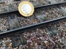
To give an idea of scale, I took a photo with a pound coin in view.

41215493922_b0191b2e90_c.jpg

Martin
 

Greengiant

Western Thunderer
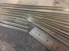
Alongside all this trackwork, the pointwork rails were being machined to shape and profile, quite tough work on rail of this size.

26387399877_8c84c03337_c.jpg

For scale comparison, a point V next to a Peco O-16.5 point.

26387402607_ee3ee9d008_c.jpg

We are working to 31mm gauge to give better looking clearances using off the shelf wheel sets, for this we have made our own gauges and done a test piece to check geometry and running.

41215500442_1f1810c8d0_c.jpg

Warmer weather today meant we could get on with sticking sleepers down, using our own drawings and photos for reference.

41215498182_6441e68698_c.jpg

It wasn't long before this lot was down.

40765303984_bf8f90539c_c.jpg

This view is from the Warren Wood side of Stony Shaw signal box, in the foreground are the timbers for the point lever mechanism. The lower timber is not stuck in place, it has to be distressed and coloured first, then it will be fixed in place.

41215499692_94b9e12141_c.jpg

For a bit of fun, we picked up a couple of these sets from GRS, lovely brass models which will be fitted with RC and sound shortly, we already have one trialing the RC. We can then use these to test the track as we build it.

39449976350_e492c960a8_c.jpg

That's all for now, there will be an update on the RotaYard once we have all the parts back from CNCing, so will be in a position to start assembling.

Martin
 

Dog Star

Western Thunderer
I have read this topic end-to-end twice now and the second reading produced some nuggets that I had missed on first reading.

How about a description of the sleeper distressing method and how the colouring is achieved?
 

Greengiant

Western Thunderer
I have read this topic end-to-end twice now and the second reading produced some nuggets that I had missed on first reading.

How about a description of the sleeper distressing method and how the colouring is achieved?
Thank you, I still have some more to post to bring it up to date.
I will try and remember what I did and do a post. When I paint and colour I have no hard and fast rules, I mix everything on the fly until it looks how I want. Quite often using multiple mediums.

Martin
 

Greengiant

Western Thunderer
Next up for the track is the painting and fitting of fish plates. These are lost wax cast from our own masters.

41316559261_f67ac5a950_c.jpg

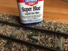
With an application of Birchwood Casey Gun Blue, the initial under coat colouring is done.

41316559071_5e3d0193f2_c.jpg

Now I have to work up colour and texture, cut the rail head but unfortunately too late to cut the rail web for the test piece, this has been handy in highlighting that we need to cut the rail web before fixing the rail in place. We don't want to cut right through the rail because the fish plates are only cosmetic additions.

27444558028_ac8d50285a_c.jpg

Cutting the head of the rail to simulate a join certainly helps, will look better when the web is also cut.


Martin
 

Greengiant

Western Thunderer
Back to the RotaYard progress.

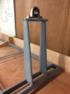
The main construction welding is now complete and the drive shaft bearings have been sourced.
IMG_0626_zpszd4zf1et.jpg

IMG_0625_zps5sdutney.jpg

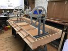
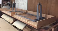
An overall view of the RotaYard in position on the two supporting baseboards.

IMG_0627_zpsgb0s735a.jpg

The drive shaft should be machined to size tomorrow if all goes to plan. We are using a boiler tube which will be machined to size in the Bredgar workshop.

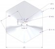
Focus turned to the end disks which support the gondolas and provide the drive to them.

Mark 1 end plate.

IMG_0161_zps6acc3qwc.jpg

IMG_0166_zpsohmjnyjp.jpg

Aesthetically this was not ticking the boxes for us, so back to the keyboard and revise the design.

Welcome Mark II.

IMG_0162_zpsohnjj3ug.jpg

IMG_0163_zpsmqs8vymh.jpg

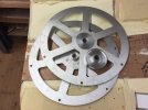
This one is a lot better, having been run and 'proved' in the CAD simulation the files were sent away for water cutting in aluminium.
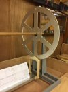
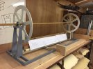
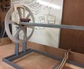
A few days later a package with two disks arrived. We mocked them up with a broom handle acting as a temporary drive shaft to support them.

IMG_0697_zpsc4aywukb.jpg

IMG_0701_zpscmd7oln5.jpg

The gears for the drive on this are due to be delivered early next week.

Here is an overall view, on the gondola are full size 16mm CAD drawings of the stock of the longest train we will be running on the layout.

IMG_0696_zps5op0axva.jpg

To give some idea of the size of the RotaYard, I placed a 7mm standard gauge wagon on the gondola.

IMG_0718_zpsieircuuv.jpg

Martin
 

Greengiant

Western Thunderer
On the RotaYard the main machining of the bearing blocks is now complete, but we do have three bins of swarf now!

IMG_1010_zpsu5lywd9a.jpg

The gear wheel is a stock item, so that saved a lot of work.

IMG_1009_zps953tba76.jpg

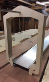
Gondola final construction has started. The gondola ends are made from two laminated pieces of CNC routed 12mm ply cut from our CAD files, to aid accurate assembly we made a construction jig.

First a perspex drilling guide jig to create the assembly jig.

42178133331_c9705fd04f_c.jpg

The jig consists of two aluminium plates with steel locating pins.

40370681360_f65aa985dc_c.jpg

The first piece of ply inserted into the assembly jig.

41277217195_99236190a0_c.jpg

With glue applied the second piece is added.

42178133191_7e4800681b_c.jpg

Then the top plate is added.

42178133181_64fcb508af_c.jpg

A side view of the jig, G clamps are applied to this then removed, cover taken off and excess glue wiped off, then the G clamps put back, clamped up and left until the glue has set.

27306310207_6734ebf525_c.jpg

After a while we ended up with a batch of supports.

41277217025_f8903375ce_c.jpg

A few spares were made so we can test out various colouring options.

42131237802_a11c554bfc_c.jpg

Martin
 

Greengiant

Western Thunderer
All of the scenic boards have been undercoated in black.

Attention turns to trimming the end profile of the first RotaYard board to match the last scenic board. The RotaYard board was left like this originally because we had a change of plan during construction, rather than go through a hole in the sky to the yard, we decided to keep it more on show and blended into the scenery rather than behind a false sky. Only time will tell if this will work as well as it does in my head!

42131238362_c578d7cafb_c.jpg

Here the board end has been trimmed and the start has been made constructing the RotaYard approach trackbed supports, which in turn leads to the traverser before entering the RotaYard.

Our intention is that the approach track and traverser track will all be made in the same weathered method as the rest of the layout. The front and rear of the RotaYard boards will be landscaped with just the RotaYard itself left in stark clinical contrast of white and aluminium, we had intended from the very start that the yard will be very much on view rather than hidden away, affording visitors a good view of the stock as it slowly rotates at 2rpm being readied for its next call of duty. I am hoping it will be like a living piece of sculpture, only time will tell.

27306313677_ef5b94bef7_c.jpg

Gradually taking shape, the traverser runners are just placed in the well.

42178132381_7f93df4419_c.jpg

This gives a good view of the RotaYard and three of the scenic boards, a further three scenic boards will be attached at the far end. Having the RotaYard on view gives us a 32' frontage with something to see rather than just the 24' of scenic frontage.

42131237822_259c7d61e0_c.jpg

Because of the curved nature of the boards and the height, it does mean neither the RotaYard operator or the station operator have direct line of sight of each other. We have a few ideas utilising small cameras which should overcome such problems, but it is very early days yet.

Martin
 

Greengiant

Western Thunderer
Having now laminated up all the gondola ends it was time to move onto assembly, for this we made a drilling jig, parts for this were CNC routed to our drawings at the same time as the gondola ends were cut.

The jig is very important in guaranteeing consistent and precise drilling.

This is the basic jig.

28476036918_39d70b0973_c.jpg

Gondola trackbed base, the sides of which have to be slightly pulled out and spring back to grip the jig.

28476037818_110b9499a4_c.jpg

Gondola ends dropped into position in the jig.

28476038858_ed1dd63e83_c.jpg

The whole assembly is turned on its side then placed in a pillar drill, I forgot to take a photograph of that part!

28476039618_62233fd3c2_c.jpg

We made a steel plate with brass tubes to guide the drills in exactly the right place and angle. The small hole between the jig and the gondola end where the drill passes through, is there purely to give somewhere for the waste wood to exit, otherwise it could well have jammed up the tubes.

28476040058_facf98d65e_c.jpg

One done, five more to go.

28476042308_0a7dc5142b_c.jpg

Alongside this the traverser approach track bed has been finished.
Here the side supports are in place.

28476048068_0d3b23d31a_c.jpg

Track wiring access holes have been cut out and the tube to take the wiring out the back has been installed.

41626669844_dcd52c855a_c.jpg

Track bed base in position.

41626671264_69d3456252_c.jpg

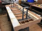
A view showing both of the RotaYard baseboards. The reason for the two castellated ribs will become clear later on.

41626673704_56732cbc86_c.jpg

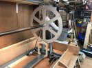
The end wheels mocked up with a temporary very undersize axle!

41626675774_67396a6bd6_c.jpg

Sleepers being glued on the traverser approach road using a real track plate to weight them down.

28518601218_498bb74792_c.jpg

Martin
 

Greengiant

Western Thunderer
The gondola pivots and bearings have been machined and matched in sets.

28518597728_d4fed2bec6_c.jpg

One of the end wheels being reamed to suit the bearings.

28518598168_107f67830c_c.jpg

The motor, gearbox and toothed wheel that will drive the RotaYard. The dark grey plastic parts are mounts we created in CAD and then 3D printed.

28518602368_220c2caf52_c.jpg

This is the adjustable idler gear we created in CAD and 3D printed, the toothed drive belt can also be seen.

28518604358_785e2b3299_c.jpg

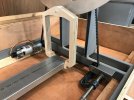
This shows the drive arrangement, in this photo the motor is bolted in place through the framework using captive nuts in recesses in the 3D printed motor mount, the idler gear is temporarily clamped in place while we mark up the frame for hole positions.

28476036328_03a1296e5c_c.jpg

A side view.

28476034458_b732616930_c.jpg

This shows the whole powered end set up with the actual axle in place and one gondola.

41447215505_deaf6b31a7_c.jpg

Finally an overall view.

28476035138_961edfee4b_c.jpg

Martin
 

Greengiant

Western Thunderer
The traverser approach sleepers are all now in place and fettling them along with those on board six has now taken place.

27840233247_686ecb9a97_c.jpg

Foam blocks have been stuck in place along most of the front, these will be carved to shape once the Gorilla glue has gone off. The foam blocks have only gone as far as the RotaYard control panel because the final design of the control panel has not been decided yet, although the surround for the panel will be made up of walls of weathered sleepers, hence the stepped element on the baseboard ribs.

Our thoughts are to blend the panels into the scenery a little more than we had originally planned. The control panel will have a mimic trackplan with switches and indicator lights for the points and signals. There will be six switches with lights, one for each of the RotaYard gondolas, there will be a switch with lights for the traverser, there will be a LCD screen with a camera feed from the station end of the layout, a series of buttons which will activate onboard uncouplers for some items of stock, there will be a 'Train ready' button with indicator lights and there will also be a panic button!

27840235417_70ef342642_c.jpg

At this end on the board you can see the start of the trackbed supports for the run-off spur from the RotaYard. At the rear a start has been made cutting the foam inserts for the back bank.

27840236157_e7665db412_c.jpg

Here the front foam inserts have been profile shaped.

27840230417_b03a6e60dd_c.jpg

Now we have the RotaYard at full size, our thoughts have changed on final presentation, initially it was going to be all white, but this we felt may too much, so the latest idea is to line the well of the yard with sheet material (see rough mock up in photo below), this will be static flocked etc. to match the rest of the layout scenery.

The uprights and gondola bases will be satin black, the water cut aluminum end wheels and gear wheel will all be left in their raw material, the gondola CNC'd plywood ends will just be clear satin varnished, hopefully like this with the Bredgar coloured rolling stock, the yard could almost look like it is floating in mid air, OK, you may need a bit of imagination for that! Only time will tell if it will work out.

27840231597_b95396181f_c.jpg

It is probably a good time to drop in an overall track plan of the layout in its now revised form.


Martin
 

Greengiant

Western Thunderer
Traverser
Just a bit of a recap about the traverser and why we have one.

The original idea of the layout was to have a single point and a hidden track disappearing behind board 6 to hold spare locos when transferring them to the other end of the trains. During discussions it was decided that this would take up time in getting locos in the correct order, not ideal at an exhibition and as the operating is front of layout, access would be a problem. So as a result the two position traverser came into being.

The idea we came up with was to use a sliding plate with two tracks, these feed the central through track and two separate holding tracks, each one long enough for a loco. The traverser had to be strong enough to carry up to 4 Kg (10 lbs), slide easily and also be positionally accurate.

In addition to being alongside the RotaYard, because it will be very visible, it had to look the part. An added advantage with a two track, two position traverser is that there will always be a track in the central position, no matter which direction the plate has moved.

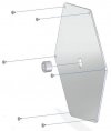
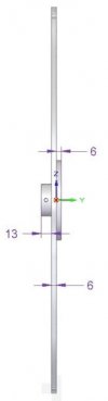
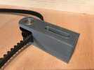
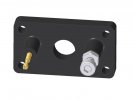
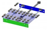
The design uses ball bearing linear motion slides and chrome steel rods similar to those used in 3D printers. The track bed or plate is mounted on the bearings and the rods are fitted to front and rear bulkheads via 3D printed holder assemblies (see illustrations below of holder assemblies).
27840221787_b6f190ecf3_c.jpg
The sector plate is made of 6mm perspex as this gave the required strength and lightness and also allows us to show the mechanical construction. The positional drive is via 6mm toothed belt and pulleys with the drive motor/gearbox fitted to the rear electrical equipment area, in keeping with the ideas used on the rest of the layout.

The final drive uses a slipping clutch so the plate can be held in either position although the motor does switch off once the slip is detected. To provide positional accuracy at each end of the plate travel, there are adjustable end stops which act on the bearing blocks rather than the plate so the centre track line up can be set at each end.

One problem that arose was how to feed the DCC to the rails. Flexible wiring was one method but it can be subject to damage and fatigue plus, in our opinion, doesn't look the part. The solution we came up with was to transfer the DCC feed at each end to the bearing blocks via pogo pins (see illustration above of holder assemblies) so the wiring is fixed. The other advantage is that as soon as the plate moves off the end position the DCC feeds are disconnected so the locos cannot move during transition.
41990678484_f8851b49f7_c.jpg
Apart from the 3D printed rod holders and belt parts, the main sector plate and front and rear plates are machined on a CNC system for accuracy. The track is hand built and matches the main trackwork.

One final requirement was that, should there be an unlikely failure in the drive system, the traverser had to be operable manually. This is the reason a belt system was chosen, by disconnecting the rear drive the traverser can still be moved by hand.

Martin
 

Greengiant

Western Thunderer
Thank you for all the likes, glad people are finding it interesting.

We have been drilling the gondolas using the jigs we built.

Here we are drilling the end supports of the gondolas, it takes some clamping, but the more accurate we are at each stage, the more it should pay dividends when we finally assemble the RotaYard.

42689564102_6eacb58920_c.jpg

Here we are drilling the gondola bases, ensuring they match up with the end supports.

42689564512_0c02dc275f_c.jpg

Finally we ended up with the six gondolas, hopefully soon we can assemble the yard and test it, if all OK it will be stripped for painting.

42689564792_917caac0dd_c.jpg

Martin
 

Greengiant

Western Thunderer
We trial fitted five of the six gondolas on the RotaYard.

27932060017_6f47c99c2e_c.jpg

41900309035_c85b4ddcff_c.jpg

27932060837_af2d9912d4_c.jpg

The gondola bases have now been painted in satin black.

43442767672_a006b680f5_c.jpg

I need to tweak some of the baseboard ribs to give a little more safety margin clearance now we have an assembled the RotaYard.

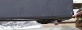
We also identified that because the motor and drive belt wheel hang slightly below the RotaYard frame (see photo below), although the RotaYard should only ever be lifted from the baseboard into its transport box, it was felt necessary to add some small feet in case it was ever put straight onto the floor.

41900295105_5fc3a4bdf1_c.jpg

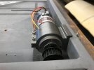
The motor in the frame fixed in place with the 3D printed mount.

41900295845_36d1c28767_c.jpg

So we needed to make some small feet and add location holes in the baseboards and storage box. A cup of tea and some biscuits later the solution was to remake the motor mount. With this in mind, back to the CAD and an offset mount was designed and we just need to 3D print one, no need for the feet.

42813770121_3690e36704_c.jpg
42813770281_73247d9ee0_z.jpg
It should not be too long now before we can do the first powered run of the RotaYard.

Martin
 

Greengiant

Western Thunderer
While all this was going on attention also turns towards landscaping, developing techniques and materials to give the impression of Stony Shaw we aim to achieve.

The base layer is earth, so what better product to represent Stony Shaw soil than the soil itself, also a lot cheaper than if we had to do this lot with scenic powders!

Excavation yielded a bucket or two full of the required soil. This was initially garden sieved to remove worms etc., then spread out in seed trays and left in the greenhouse to dry out.

39671158000_a7e2c917f6_c.jpg

After about a week the dried soil lumps were crushed by hand into smaller bits, these were then ground using a pestle and mortar.

39670240040_3838af91fc_c.jpg

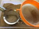
The resultant grindings were further sieved through various kitchen utensils until we had four sizes of soil grain.

40588348435_4167985ba6_c.jpg

The finest of which is not far off that of cement powder and will be used as a filler once the coarser grains have been stuck in place.

39670278690_d12b95a881_c.jpg

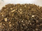
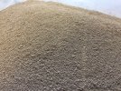
The next size, which is the one we will probably use the most of nicely captures the various types of particle in the soil.

27607282178_054031a84e_c.jpg

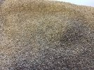
Size up again gives a nice selection for areas requiring a coarser texture.

41436508132_6979ebfee6_c.jpg

Martin
 
Top