mickoo

Western Thunderer
What an elegant solution :thumbs:

I'd need a slightly larger clearance hole in the floor for the tube to pass through and then a correctly sized one for the fixing under the footplate.

Or an oversize one in the footplate to let the screw head pass through and the correct one in the floor for fixing, either option works well and easily instigated in the design stage of the etching.

To move on from both suggestions above, it'd be easier still to simply solder a nut inside the base of the tube, simply pick a tube diameter that is a snug fit over the required nut.

A thin oversize washer near the top outside of the backhead would then hold the backhead into place against the floor as well.

Mick D
 

Steph Dale

Western Thunderer
Mick,
A tapped tube will be smaller diameter than a tube with a nut in it. Other than that I guess you've cracked it!
Steph
 

mickoo

Western Thunderer
Mick,
A tapped tube will be smaller diameter than a tube with a nut in it. Other than that I guess you've cracked it!
Steph
Indeed, but only works if you have a selection of taps or the prospective builder has, but if not then anyone can solder a supplied nut into a supplied tube, just thinking that everyone might not have the tool set we have collected over the years.

Failing that just solder the nut to the inside of the roof in the designated place and fix with a screw of prescribed length, lining up might be a problem so a tube as a guide would help, one that goes from the floor to just above the back head to hold said item in place.

There are many ways to achieve the same result, some more eloquent than others ;)

The only fly in the ointment is that your going to be using a fixing that is on the underside of the raised section over the safety valves, to form this easily and uniformly the material is half etch and thus compared to the rest of the roof, quite thin, if you over tighten you run the risk of buckling that thin sheet.

I'll explore some more during the week.

Mick D
 

Silverystreaks

Western Thunderer
Mick

You quite rightly highlight the fact that the rod in this case has to be soldered to a very narrow and thin area underneath the cab roof etch and yes this could lead to buckling if over tightening occurs.

I have to say though I have not experienced that. However, the criteria must be to start off with a cab roof that can already sit comfortably and accurately into its position. That is for the A4 and V2 within the V shaped cab front and then each side-sheet. If it has to be forced down into position on tightening the nut you will run the risk of buckling, or the rod breaking away from its soldered position.

I recall prior to going off to the paint shop the A4 had a final run out on the clubs layout. Unfortunately I had overlooked its fitness to run exam and during one circuit the front bogie wheel came adrift and the loco ended up on its side. Luckily no damage occurred and the cab roof remained in situ. It has had plenty of handling over the past seven or so years as have the V2 and A3 all without the cab roofs being a problem

Regards
Bob
 
Last edited:

mickoo

Western Thunderer
Bob,

The Finney raised roof section I think is 15thou brass and reasonably easy to form to shape, the W1 is nickle silver and forming that small curve on such a small piece consistently and uniformly is nigh on impossible, well I found it so and I'm on my third cab now! So, on the W1 that raised section is very thin half etch 7 1/2 thou which then sits in a recessed lip on the main roof.

The hump opening in the roof is the full area of the raised section, on the A4 I think I recall the rear triangular piece being solid and part of the cab roof and a small triangular section just soldered on top. I'd have to check the kit to be exactly sure though.

It has set my mind wandering, I may be able to hide a small, or add a small, bridging piece between the safety valve opening and vent opening, it will cover up the detailed overlay underneath the vent runners but in reality once it's all completed the view up there is limited to say the least.

Another option is a small tube down the front of the window frame assembly through the floor to just above the footplate, it'll be mostly hidden by the back head when in place, a small piece of wire is then discretely soldered to the cab roof, passed down the tubes and simply folded over under the footplate, that will hold down the front outer corners which is the area hardest to secure.

It would also hold the cab square and prevent any racking. Over time the bending of the wire would weaken it, but how many times does a roof need to come off, and if it did fracture you just clean that small discrete area in the top front corner of the cab roof and fit a new piece.

A 1.0mm ID tube should be more than discrete enough to hide up the front, even better a square section tube would look less out of place. I think another on the front wall near the crown where the roof hump starts would hold that section down as well.

My one over riding factor in all of this is that there must be no visible gap between the cab front and roof and until recently soldering was the only way I could see around this.

The tail end of the cab roof has the rear angle curled round to fit inside the side sheets, a small dab of reasonably strong adhesive would secure that, perhaps even a dab of 100°C solder.

I'm still exploring making the whole cab floor removeable like the West County / Battle of Britain model, that'll allow better access to the side windows and front windscreen from inside, but then that also means that the whole cab assembly needs to be able to be removed from the footplate, currently that's not the case and once it's soldered to the footplate it really needs to stay there.

Mick D
 
Last edited:

mickoo

Western Thunderer
Ok a real quick test.

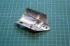
A small bridging piece stuck across the thicker part of the cab roof with double sided tape, there's probably enough of a gap to fit a 10BA nut behind it.

IMG_7106.jpg

Proposed tube (red) up through backhead area, without the cab shell you can see the gap under the floor to the footplate, tube to pass through floor and stop short of footplate by 0.5 mm or so, the problem is that the footplate or floor might flex so limiting the gap limits deformation. The tub is fixed to the floor and protrudes just proud of the firebox crown to locate the backhead assembly. I may add a small lower locating plate on the backhead assembly to stop it sliding around (green).

Small note, the brass backhead spacer is too short and will extend forward by another 3-4mm to position the backhead in the right place in the cab, looking at the GA for the A4 I think this needs to be done as well on those models, I.E the backhead is too far forward on the A4 model and does not line up correctly when viewed side on with respect to the windows or lower foundation wash out plug, but I need to measure the model and cross reference with the GA to be absolutely sure.

IMG_7111.jpg

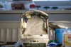
Low angle view into back of cab, you can just see the bridging piece.

IMG_7114.jpg

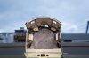
Ultra low angle and barely visible

IMG_7117.jpg

Mind this area is partially hidden by the steam turret / manifold

IMG_8648.jpg

Looks like winner winner chicken dinner, I'll still run with the front corner tubes to line that area up and as additional fixings. Smallest square tube is 2 x 2 mm so I'll run with tube of 1.10 mm ID.

Mick D
 
Last edited:

mickoo

Western Thunderer
Finally got around to sorting the roof fixings, follows exactly as described above. Having completed that I thought it'd be a therapeutic end to the week to get the crayons out.

Primer was Acid 8 etch which, for some unfathomable reason, surprised me when it came out of the can as grey, I was expecting black but for no other reason than I did. Still grey works for me, so all the parts were duly primed and then top coated.

The roof and floor, both detachable were then sprayed Halfords Satin black, nice colour and lays well, the Halford nozzles do really give a nice spray for a rattle can. The cab sides and front were then sprayed with Land Rover Bronze Green from a rattle can purchased from Autopaint Solutions, Doncaster, it's a cellulose paint and again lays really well with a good nozzle on the can.

Then the problems came, the cab floor slots into the sides with tabs, un-painted they are a snug fit, painted, they don't fit, bleedin obvious really but something I totally failed to take into consideration, luckily they are all hidden tabs so the paint was scraped off and the parts joined.

The reason for keeping the floor separate was for painting, it's black all over and the cab interior is engine colour, the future choice is to just mask the tabs, of make the slots bigger. The problem then is for those who wish to fix the floor in place and paint it all as one as the slots will be sloppy.

Still it is what it is and once all fitted together does look rather nice.
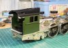
Image3.jpg

Next just for giggles I pushed the A1 tender up to the engine to check the fall plate and basic heights.
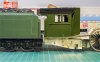
Image2.jpg

Bother, wasn't expecting that :eek:

No issues with the mechanical aspects, all spot on, the tender is weighted a bit too heavy so sits a bit too low, however it was the colour, totally different.

Both colours individually look right, but together they are miles apart, which is strange as they both came from the same can!

The tender under coat was black, the engine was grey, which is at odds with the shades as the paler green has the darker undercoat, the tender has not been in the sun, but on a shelf tucked up away to keep dust to a minimum.

Given that the photo is inside and the lighting is giving it a warm bias the one on the engine looks a better shade.

Having said all that, and whilst writing this I dimly recall the original search for the correct colour and using cans as test subjects, Cider I seem to recall and the infamous Halfords shop mixed exploding cans. The tests involved Pheonix paints and Halfords Land Rover Bronze Green and another I think, I thought it was AS,Doncaster, the winner going onto the A1 tender, but I'm begining to doubt it was AS paint on the A1 tender now.

Time to go back through that saga and try to work out which paint the tender actually got painted in.

Moral of this tale, paint everything at once... from the same source, not two years apart!

MD
 

warren haywood

Western Thunderer
Mick,
Can't imagine it's the undercoat, green is a very dense pigment so you must have used different paints. The one to the right looks better to my eye but then it's a photo so.......well you know;)
 

mickoo

Western Thunderer
Warren, going back through my original saga early last year it looks like I ended up using Halfords shop mixed Land Rover Bronze Green, there being six different shades to choose from and I tried two which were only slightly different, so I suspect they are all different compared to AS cellulose.

I'm inclined to agree with you in that the loco looks the better colour, it's a deeper green and just feels right.

The next question is what to do with the A1 tender, the Halfords paint is an acrylic I seem to recall, I wonder if I take it carefully and with very light coats can re paint the tender in the AS cellulose.

One interesting thing that came out of this little jaunt was the effect of black marker pen, I'd left a mark on the inside from construction and the etch primer hasn't damaged it or reacted with, nor the green cellulose over that. It's inside the cab and the green layer is behind the back head so quite a thin coat. Anyway, black marker is very resilient and requires some abrasion to get it off the metal so I'm wondering if it might pay to use it as a pre coat on areas that are prone to damage, such as step edges, foot plate edges (note tender above has some damage already), thus if the paint is chipped off it'll reveal the black marker underneath.

Certainly easier to apply than chemical blackening, I feel another experiment coming on ;)

MD
 

Peter Insole

Western Thunderer
Mick,

Halfords used to do Landrover "Coniston Green" (LLR1) in their decent pre mixed rattlers. It was an EXACT match with my original paint samples!

Incidently, the colour also matched genuine paint chips acquired from an unrestored BR class 37 many years ago and several types of DMU. Perhaps what was most surprising is that I got another precise match when I took a swatch and offered it up to the rather sad and peeling Lynton and Barnstaple carriage at the NRM revealing that the LSWR and Southern Railway, Maunsell "Sage Green" was in fact the same shade - just a different name!

You might not think that was the case on some preserved loco's and stock?

In the end, I don't fully trust restoration efforts, however well intentioned, preferring to rely on the real thing wherever possible. Modern paints behave differently anyway let alone the effect of contemporary prep, prime and undercoating methods!

Pete.
 

mickoo

Western Thunderer
I grabbed a picture in the sun, brief as it was. Rather than a bland background I posed the plant tray so that I could get a decent colour fixed point when editing the image, it's easy to adjust for one colour and get the rest wrong, everyone knows what colour a potting cup is so if that's the right hue then it stands that the other colours are also right.

IMG_7517.jpg

I think the AS cellulose is the winner on the engine, amazing as on it's own the tender looks right as well but it'll be in for a respray shortly, hopefully I'll simply blow over the existing paint, I think it's an acrylic so the cellulose shouldn't attack it too badly if the coats are light and often.

I need to finish the roof, I've a niggle that it should be green below the rain strip and match the tender paint profile, after that a trial fit of the glazing to see if the slotted design I've designed works, too late now if it doesn't really. I might even have some numbers somewhere but lining I'll leave to the experts ;)

MD
 

mickoo

Western Thunderer
Ok, where were we? Time to blow the dust off this little wee beastie and crack on.

Before the Bulleid light pacific I was fumbling along with the bogie and rear carrying axles and found space for a few other parts and decided over the Xmas break to set about the brake gear which is quite complicated. I''l say here and now, what y'all see here may not be in the final model, or in this guise, this is why we have a test build, a: to see if it all actually fits and b: to see if it's even practicable. At the end of the day it has to be build-able so miniature replicas of the rear thing are often, as nice as they would be, not practical.

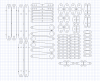
At the moment it's just etch work, but laid out there's 46 individual parts to make up the brake gear, some of these can be joined as larger etches in the second run if required and some parts lead them selves to castings with etch work around them, though if you really want to build it all up like the real thing from all of these links....you're more then welcome ;)

Image2.png

Still missing are the main brake shafts and rear cylinder pull rods and a couple of brackets. I did think the Bulleid brake gear was fiendish but the W1 has an extra two shafts that run back across the main brake shafts to link the front and rear cylinders, I'll work up some drawings, mainly to help me build it but they will fit right in to the instructions and help others understand how it all goes together.

Hopefully all of this, the bogie and rear carrying wheels will be ready for sending to PPD at the end of the weekend, which then leaves time to work up the valve gear. Which looking at the model sat here, is about the last of the etch work to work up. There are of course castings to do but it's getting closer now to being finished.

MD
 
Last edited:

mickoo

Western Thunderer
Well, that was a productive day, including a lay in ;)

Chopped some wood, finished off the etch work for the brake components, made up the instruction diagram (below) but still requires numbering and spent the afternoon with a little father - son (21 now, which is handy as I don't have to take him to the bathroom any more, though I still have to point him there when he comes home from the pub sometimes :rolleyes:) time watching the latest Star Wars movie.
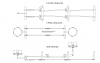
Image2.png

As one can see, it's a rather complex affair, actually much like an A4 though I've never seen the upper linkages ever modeled, which is a shame as they are most certainly visible through the wheels, as they are on the W1.

The W1 uses two enormous 27" drums where as the A4 uses three 21" drums, the front one on the W1 being replaced by two side by side on the A4, but overall the arrangement is much the same.

Right, on to the valve gear :thumbs:

MD
 
Last edited:

mickoo

Western Thunderer
Exactly like that and do I spy the correct tread chamfer as well :thumbs:.

What's the gap between the fixing plates? The W1 has etched brake hangers 0.8 mm thick and I've allowed 3.5 mm between fixing pin centre and shoe face.

Image3.png

Mick D
 

mickoo

Western Thunderer
Part worn then ;) perfect :thumbs:

Have you run a set off yet to see if they form correctly, mind seeing some of your other work I see no reason why these basic shapes won't form correctly at all.

Mick D
 
Top